


STEM Career Connections Start Early: Celebrate Techie Kids This National Techies Day
October 1, 2025
Planting the Seeds of Innovation: STEM in Agriculture
November 3, 2025Electrifying STEM!: A Crash Course in Circuitry, Part I
We here at STEM Education Works are big believers in the idea that, whenever possible, STEM learning should be a hands-on, interactive experience for young, inquisitive minds. And there is no better example of this than building and tinkering with electrical circuits!
Circuity is an engaging subject where theory and experiment come together to really put your students in the mindset of real STEM professionals, helping them build their reasoning, math, and iterative learning skills along the way. With this in mind, today’s blog is meant to help you build up your understanding and confidence when it comes to all things circuitry.
The Basics of Electricity and Electrical Circuits
Electricity is defined as a form of energy created by the flow of electrons along a certain path (i.e., an electrical circuit). All matter has electrons in it (at least the type of matter that we usually interact with), but some forms of matter allow electrons to flow through them more easily than others. These materials that allow electricity to easily flow through them are called “conductors,” while materials that are resistant to the flow of electricity are called “insulators.” For obvious reasons, most electrical circuit components are made out of conductive materials.
You can think of an electrical circuit as being like a racetrack where racecars (electrons) can travel along a designated path and end up right back where they started, ready to run another lap. Electrons in an electrical circuit essentially do the same thing, with the key idea being that the components of a circuit must form a complete, continuous loop to allow electrons to continuously flow through the circuit.
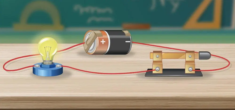
Even the most basic electrical circuit will have at least three components: a power source (like a battery), a load (like a light bulb), and some metal wire (or some other kind of conductive material). The power source is what provides a circuit with the driving force or “pressure” needed to “push” the electrons through your circuit. A load is any sort of output device that converts electrical energy into another form of energy, like light, heat, sound, or even motion. And the metal wire serves to simply connect your circuit components to form a complete loop, allowing your electrons to flow as long as your power source keeps pumping.
You can see an illustration of a simple circuit in the title image of this article. In the example above, a switch is also included, which allows the user to turn the light bulb on and off at will. When the switch is closed, electricity is allowed to flow freely through the circuit, and the light bulb turns on. And when the switch is open, electricity is not allowed to flow through the circuit and the light bulb, deprived of its energy source, turns off. Because when circuit components no longer form a complete loop, the electrons in the circuit can’t fully “feel” the influence of the power source, and no electricity flows.

Voltage, Current, and Resistance
When it comes to circuitry, voltage, current, and resistance are the three most fundamental values that define the properties of a circuit.
Voltage is measured in volts (V). Remember how I previously said that the power source in a circuit provides the driving force to push electrons through a circuit? Well, you can think of voltage as being the amount of driving force that a power source provides to push electrons through a circuit. So, for instance, a 9-volt battery will supply a circuit with 9 volts of what we call “electric potential.” (You can think of electric potential as being kind of like energy, but not exactly in the same units as energy.)
Resistance is measured in ohms (Ω). You can think of resistance as… well… the level at which a circuit resists the flow of electricity. Many kinds of circuit components can contribute to the total resistance in a circuit, like load devices and resistors.
Lastly, current is measured in amperes, or “amps” for short (A). Current is essentially a measurement of how fast electrons are traveling through a circuit. While the voltage in a circuit is directly determined by the power source used, and the total resistance in a circuit is directly determined by the circuit components used, current is less “fundamental” to a circuit, in the sense that it sort of “pops out” as a result of the voltage and resistance being used in a circuit.
Ohm’s Law
Ohm’s law is what really brings all of these ideas together, describing the relationship between the three basic values we just discussed: voltage, resistance, and current. It states that the voltage in a circuit is directly proportional to the current in that circuit, with the total resistance in the circuit playing the role of the proportionality constant. It can be written as
V=I*R
where V is the voltage in the circuit, I is the current, and R is the total resistance.
And the really cool thing about Ohm’s law is that it can not only be applied to the entire circuit, but it can also be used to analyze smaller, individual parts of a circuit. Wanna create a circuit with 0.05 A of current flowing through it using a 5 V power source, but you don’t know what kind of resistor to use to make this happen? Well, just divide 5 V by 0.05 A and you get 100 Ω! So grab a 100 Ω resistor and splice that bad boy into your circuit! Do you have a circuit with 2 A of current flowing through it, and you specifically want to know the voltage drop across a 6 Ω resistor within that circuit? Just multiply 2 A by 6 Ω and *BAM*, you got 12 V! You’re a circuitry wizard now. Welcome to the club!
Conclusion
As you can see, the concepts and math behind circuitry are actually rather simple once you play around with them a bit! And as with any STEM subject, the more comfortable you are as a teacher, the easier it will be for you to help and guide your students to become STEM champions!
If you’re interested in supercharging your STEM classroom with circuitry, be sure to check out our website! For younger students, our Brown Dog Gadgets kits offer a perfect mix of circuitry and crafting! For older students, our Build Smart and micro:bit kits are an excellent way to bring the worlds of circuitry and coding together in your classroom. And to sprinkle a little VR technology onto the subject of circuitry, be sure to check out our MindLabs products! Not to mention our Horizon Educational kits, which combine circuitry with renewable energy concepts.
Even though this blog has come to an end, there’s still more to be learned when it comes to electrical circuits. So be sure to catch Part II of this blog in the near future, where we’ll dive into series/parallel circuits, common circuit components, and my favorite, breadboards!
Until next time.
– Dr. Jake Roark


